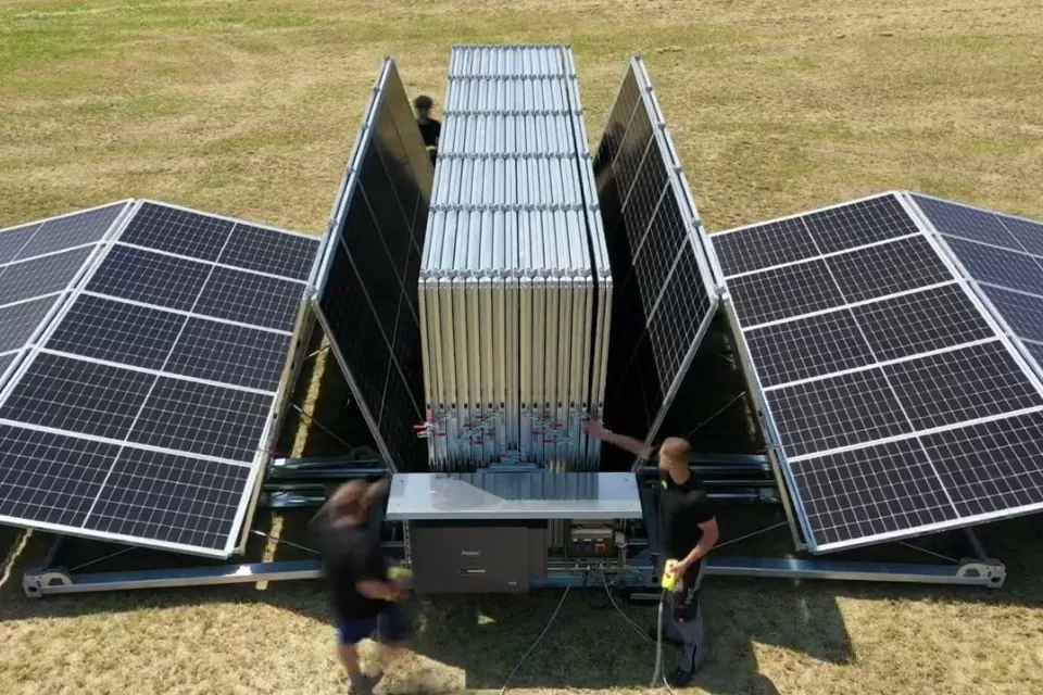
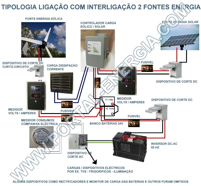
A seguir apresentamos um esquema de uma tipologia de ligação e interligação de duas fontes de energia (aerogerador e painéis solares fotovoltaicos) com armazenamento de energia em baterias.
Controlador Carga baterias – É obrigatoriamente necessário um controlador.
O objectivo principal de um controlador é prevenir o sobrecarregamento das baterias e consequentemente diminuir a necessidade de troca das baterias devido a deterioração interna.
Outro ponto importante nos controladores são os algoritmos para aumentar a longevidade dos bancos de baterias. Existem diversos modos de carga como evitar que a bateria descarregue completamente, equilibrar as cargas, etc.
Por último mas não menos importante é a capacidade do controlador em maximizar a carga produzida pelos pontos de geração e induzi-la nas baterias.
Controladores de carga existentes no mercado por ordem de complexidade e capacidade
– 1 or 2 stage controllers
– 3 stage or PWM controllers
– MPPT (Multi-Power point tracking) controllers
.
A informação seguinte está em inglês para uma maior compreensão de nomes técnicos.
1 or 2 Stage controllers
Also referred to single or dual voltage charge/diversion controllers. These controllers are by far the simplest in design as they generally rely on a relay or set of relays to disconnect or divert an energy source or load when the battery voltage reaches a certain point. They can range from a few amps to hundreds of amps capacity and are often limited only by the capacity of the relays they are switching.
They do not offer battery maintenance charging (such as equalize charging) as they simply monitor the battery voltage and “trip” at a certain level. They can be very economical and very reliable as they are simpler in nature and therefor have fewer components to break. Newer model single stage controllers offer microprocessor controlled circuitry allowing for more precise and stable operation.
Who should consider this type of controller:
You have or will have a wind or hydro energy source.
This type of controller can be wired as a “Diversion Controller”. In this mode, when the batteries reach their high voltage trip point, incoming energy is diverted away from the batteries to a diversion or dummy load, while allowing the charge source (wind turbine) to stay fully loaded. It is very important that wind turbines remain under load, particularly in high wind events or there is a real chance they will over-speed and be destroyed.
Although some PWM controllers can also be used in a diversion mode, when they are utilized in this fashion, they, for all practical purposes have been set to mimic a single stage controller. If you have a wind turbine, it must have a load on it at all times, so all of the other technologies cannot be fully incorporated for a wind turbine.
There are indications that some of the larger controller/inverter manufactures are working on more advanced MPPT controllers for wind energy, but at this time there really is nothing better (in my opinion), for wind energy then a single stage, diversion controller.
You have a solar only system but your budget does not allow you to purchase a more advanced technology controller.
Single stage controllers are often very economical and generally offer much more capacity per dollar then PWM or MPPT controllers. Keep in mind, this type of controller does not offer the level of battery maintenance charging that the PWM/MPPT controllers do.
You have a more advanced controller for normal cc, but you also have a wind generator and need to have an insurance policy against overcharge in high wind conditions.
In this situation, your solar panels are routed though your PWM/MPPT controller. Under nominal conditions, the turbines power is seen by the solar charge controller (due to and increase battery voltage) and and when necessary the solar energy that is allowed to flow into your batteries is reduced or cut off as required; however, the turbine is allowed to stay fully loaded. This is a very good compliment of controllers and works well, even in the largest of solar systems.
You have a backup generator and want to insure that when it is running, your batteries remain fully protected from overcharge.
Most inverters designed specifically for alternate energy systems have a generator start /stop capability. If this is the case, the inverter itself is the charge controller, and you will not need this additional protection from a single stage controller. However, if you have a generator that is manually started and not controlled by the inverter, then using a single state charge controller to insure against battery overcharge is a good choice.
Who should NOT consider this type of controller:
– You do not have a wind or hydro turbine and have a sufficient budget to purchase a more advanced controller.
– All of your charge sources can be routed through your PWM/MPPT controller or otherwise controlled.
Multistage, 3 stage or PWM controllers
PWM (Pulse Width Modulated) controllers are solid state controllers that offer more advanced charging algorithms than single stage controllers are capable of. First lets talk about the PWM aspect.
As the battery voltage increases, the charge controllers primary responsibility is to restrict the incoming voltage (and current) to insure the battery does not over charge. The simplest way to do this would be to open the circuit (turn off the internal switch), when the battery gets “full”, but of course as soon as you do this, the battery voltage will start to drop and the controller will need to turn the switch on again.
This on and off switching, then would attempt to keep the batteries at a full charge state and everything would be fine. Turning on and off repeatedly is no problem for a solid state device, but it really is not that simple. It is better if the charge voltage/current to the battery varies based on its state of charge and where the battery is in its overall charge cycle (Was it nearly depleted, or has it been mostly charged now for awhile and just needs to be maintained?)
There are many different philosophies used, including 3 stage charging, constant voltage and tapered charging, but for the most part, to promote better battery health, batteries are not just brought up to full charge then shut off by a multistage solid state controller.
The controller examines the batteries state of charge and as it progresses through the charge cycle, reduces or increased the current as required. Once the battery charge cycle is complete, the charge controller will reduce the current even more to hold the battery at the “Full State”.
So this is what the controller does, but it does it via pulses of energy that may last from less than a second to several minutes. The term pulse width modulation is really pretty simple to understand.
If you had a garden house with a hand held nozzle that you can turn on and off by squeezing the trigger, you could easily control the water volume to say 50% by simply squeezing the trigger half way, or conversely, you could, by repeatedly squeezing the trigger once every two seconds for a full second on, and a full second off accomplish the same thing. Each time you squeeze the trigger it’s a pulse, the length of time you hold the trigger is the width of the pulse.
Basically, if you turn on the water on every second, and off the next second, then you are letting 50% of the water that is available to pass though the nozzle. If you where to hold the trigger for 1.5 seconds on and .5 seconds off, then you would be allowing 3/4ths of the volume to pass. This is what PWM controllers do. This pulsing action is much easier on the charger (most current carrying electronic switches heat up if they are half way on, but they don’t mind at all if they are full on and full off many times a second). But there’s an even bigger reason why this is done — The batteries love it. These pulses of energy are much better on the plates of the batteries then a steady high voltage D/C charge.
So PWM controllers allow an electrical pulse from the charge source to pass, that can be better for battery life then steady state charge currents. Some PWM controllers will incorporate high frequency switching. The same basic on/off cycles are used, but much much faster (Many times a second), sending very fast short burst to the batteries.
These short burst of higher currents can be very effective on keeping the plates of the batteries in good health. Not all PWM controllers are the same, some use high frequency pulses, others use pulses only as the batteries reach a higher state of charge, but all PWM controllers incorporate pulses of energy of varying frequency to control the actual current to the battery.
The main advantage to solid state controllers is that they offer more advanced charging modes than single stage controllers. We will briefly discuss the three stage charging mode.
– Bulk Charge
– Absorption Charge
– Float Charge
The 1st stage in a 3 stage charging mode is the bulk charge: In this mode, most of the available current is sent to the batteries until they reach about 80% of the capacity. Generally the bulk charge rate is set to between 13.5 to 15 volts. There is really is no perfect voltage setting here as there are many factors involved.
The ambient temperature, the size of the energy sources vs battery size. The desired length of time in this mode, the cost of the energy if it is supplemented by the grid or generator, etc. — Simply stated, the bulk charge gets the battery up to a mostly full state in a quick but healthy rate. Common low cost automotive charger uses the bulk charge mode as their only charge stage. The voltage is simply set to perhaps 14 volts by the charger, and that’s that. This really is not very good for long term life of the battery.
The 2nd stage of the 3 stage charging mode is the the Absorption Charge: As the battery gets full, it, due to internal resistance accepts less charge current. During the Absorption charge, the charger will hold a slightly higher voltage to overcome this. During this stage, the current flowing into the batteries will still be less, but the voltage will be higher.
Via this stage, the the battery will be brought up to its maximum capacity (Fully charged). Again, the voltage setting varies from controller to controller, but is more dependent on the battery type and temperature, then the bulk charge is. For a 12 volt lead acid battery, you would expect an absorption charge voltage of between 14.2 and 15.5 volts. During this stage, battery gassing is normal and required in order to complete the chemical reactions to obtain a fully charged battery.
The final stage is the Float Charge: This mode is the charge mode that the battery is under most of the time for a properly designed system. Once the batteries are brought to a full state of charge, the float charge mode maintains the batteries at a voltage level of about 13 to 13.2 volts (for a flooded, 12 volt lead acid battery), by applying pulses of current as required.
These pulses may last less than a second or be several seconds long. By applying the required amount of charge current to offset any load the battery might be powering, as well as overcoming the batteries natural self discharge, the batteries longevity is greatly increased. Allowing a battery to set in a depleted state of charge for long periods of time significantly reduces battery life. A decent battery, kept at is proper float setting, will last many years.
Another charge mode incorporated by many chargers is the equalize charge. This mode is not a part of the normal charge cycle, but is instead initiated manually to help mix the electrolytes of the battery. During normal use, a batteries chemical mix becomes stratified. (Separated from top to bottom). An equalize charge uses an approximately 10 percent higher voltage, to help mix these elements in your battery.
Equalize charging also helps bring all of the batteries in a multi-battery bank to an equal state. Most people agree that an equalize charge should be run once every 10 to 40 days, for 2 to 16 hours. During this charge cycle quite a lot of gassing will occur, which causes the fluids to be mixed and the plates to be “Cleaned”
Well made, multistage charge controllers are recommended for solar only installations or solar and wind installations where only the PV panels will be routed though the 3 stage controller. Multistage stage controllers are not recommended as the only charger for systems incorporating wind turbines.
Wind turbines must have a load at all times. A 3 stage, or multistage controller does not allow the turbine to see a full load at all times which may allow damage to occur to the turbine, from over speed in high wind conditions.